Lab 4 - Introduction to Network Configuration and Packet Capture
EEE/GEF 473 - Winter 2015
References
Objectives
This lab aims to:
- Introduce you to the set-up of an internetwork
- conduct a preliminary examination of the ARP protocol
Introduction
In this lab you build on the basic network principles and diagnostic techniques introduced in the last lab. You will build a small network consisting of two sub-nets connected in a larger network using a router. You will examine the nature of the packets that flow through a gateway to a remote network. Emphasis will be placed on the interaction of layers 2 and 3 in the protocol stack that enable inter network communication. Part of this investigation will include the use of ARP to manage the layer 2 to layer 3 address mappings.
Part 1 - Building a small internetwork environment
You are to build a small network consisting of two separate sub-networks. Take the time to first plan the structure of the network. Each team of students will set-up a Team Network that will in turn be networked with every other Team Networks and the Common Network.
Note that during the majority of the course, the Common Network is part of our Local Area Network. In this lab, however, the Common Network is playing the part of the Internet or Wide Area Network.
- Recall your unique value of
x. Recordx: _______
The inter network is partially described in Figure 1 and should have the following properties:
- Your Team Network:
10.30.x.0/24
- Your Windows VM (External Adapter) will be on this sub-net and
have IP address
10.30.x.10: - A Common Network :
10.27.0.0/16 - A Core Server VM on address
10.27.0.1. This server is aliased to also respond to every Team Common Server. The instructor will give an explanation of IP aliasing at the board. - A Core Printer on address
10.27.0.8 - A Team Common Server VM on address
10.27.x.1; this Team Common Server VM will act as the Team Common Router. - A Team Router whose interfaces are
10.30.x.1and10.27.x.30 - Begin to fill in the blanks on Figure 1.
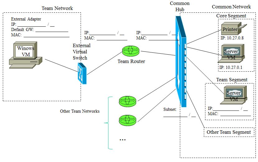
Figure 1 - Network for Lab 4
You have available as materials:
- A Windows VM
- A Cisco 881 Router with an integral 4-port switch
- Common Network infrastructure:
- The Patch Panel and Common Hub in the cage
- A Common Network Core Segment containing:
- A Core Server VM
- A Core Printer
- A Team Common Network Segment containing the Team Common Server VM
- 1 green cable in the cage and one yellow cable for the Cisco 881 Router
Follow the steps below to get your network up and running.
Part 1a - Configuring the Cisco 881 Router
Disconnect the green cable from the green port on the desk (directly in front of you). Connect this green cable from your host computer to one of the Team Router's LAN ports. Connect the yellow cable from the Team Router's WAN port back to the green port on your desk.
The Cisco 881 comes with a factory setting that allows it to be
configured using an on-board IOS (Cisco Internetwork Operating
System, not iOS from Apple) accessed via the integral 4-port
switch. By default the router has a DHCP (Dynamic Host Configuration
Protocol) server running so that any computer that plugs into the
4-port switch can request network information and automatically
configure itself to talk on the router's default subnet on the 4-port
switch. That is, the computer plugged into the router will be
assigned an IP address and netmask by the on-board DHCP
server and the computer will use that information to automatically
configure its network interface. We will use this default subnet as a
temporary network for initial configuration of the router and then
reconfigure it to achieve the sub-nets as described above.
- Power on the Team Router.
-
Control Panel -> Network Connections ->Select External interface-> Properties -> Internet Protocol (TCP/IP) Properties ->Select "Obtain an IP address automatically" - Recall that you have to close the properties window to ensure that the setting will take effect.
- Select
External interface -> Status -> Supportor useipconfig /all
(#1) What is the IP address/netmask given to your Windows VM (answer
with both CIDR notation and netmask)?You should have observed that the
IP address is in the 10.10.10.0/29 network.
(#2) What is the IP address of the router?
Telnet to the Team Router. The login user id and password
is "cisco" / "cisco". If this worked you
should see the user prompt yourname#. Do not type your
name!
configure terminalusername cisco privilege 15 secret 0 cisco
no ip dhcp pool ccp-poolaccess-list 23 permit anyinterface FastEthernet 4ip address 10.27.x.30 255.255.0.0no shutdownip route 0.0.0.0 0.0.0.0 10.27.x.1interface Vlan 1ip address 10.30.x.1 255.255.255.0
As soon as the last command is entered you will lose contact with the Team Router. (#3) Why is that?
Reconfigure your Windows VM External
adapter (IP address 10.30.x.10 netmask 255.255.255.0)
to connect to the newly configured Team Router. Note that this
time you will also need to include the default gateway. Refer to
your completed Figure 1 if you are not sure.
If everything is set up correctly, your Team Router is now configured
to route packets that are not addressable on its Local LAN (the Team
Network) to the default gateway address (the Team Common Router at 10.27.x.1).
However, the Team Common Router in the Common Network is not aware of
the sub-net you just created and does not know that it must send packets
destined for your Team Network to your Team Router; the laboratory
instructor needs to add a route to the Team Common Router that tells it
that your Team Router is the gateway for your new Team Network.
Make sure you understand why this is required.
Read the route man page on the Linux VM (the route
syntax is different under Windows). You need to craft a command
to add a route for your Team Network on the Team Common Router; note
that command in your lab report and explain why it is necessary (#4).
Call the instructor over to discuss and he will include your route when
he is satisfied.
From this point forward, you may want to consider recording your traffic so that you may refer to it later when you are not in the CNSl. Review Part 4 of Lab 2 if you need a reminder.
Now that your network is up and running, make sure that you are able to:
- Ping the Team Router's LAN interface (
10.30.x.1) - Ping the Team Router's WAN interface (
10.27.x.30)
- Ping the Team Common Router (
10.27.x.1)
Telnetfrom your Windows VM to the Telnet server (10.27.x.1) usingalice/secret
- From alice's account ping back to your Windows VM (
10.30.x.20) - Print a single test page.
(#5) Report any difficulties and/or changes you had to make in order to get your network up and running properly; be specific. Clearly state if you had no problem.
Part 1b - Sniffing with windump
Familiarize yourself with windump again, particularly
with the -i -e -n switches; provide a summary of these
switches in your lab report (#6). When running windump in
this lab we will be interested is seeing the numeric format for the MAC
and IP addresses. You should use the -n
switch to avoid lengthy delays. You might also notice that there is a
lot of spurious network traffic generated by Windows that makes it hard
to see the traffic you are interested in (e.g. your telnet or
ping packets). You can filter this out by identifying what
host or TCP port is involved with the spurious communication and
excluding it from your dump traffic. For example if you find your output
cluttered with Windows packets relating to ports 137 and
1900 you can use the command:
windump -n "not port 137 and not port 1900". This will eliminate traffic on those ports from your output.
A suggested alternative is that you "filter-in" the traffic by only
selecting the hosts and protocols/ports of interest. For example,
if you want only the telnet traffic for any hosts on your
local sub-network, you might use:
windump -en "tcp port 23 and net 10.27.x.0/24"
IPaddresses for all interfaces on the inter network (if not already done so), and
MACaddresses for your Local Network sub-network.- Ensure that the diagram is reproduced in your lab report (as Annex A); here is the source file.
Part 2 - Analysis of network packet capture data
The Address Resolution Protocol (ARP)
As you know, ARP is used on the local subnet to find the MAC address
that corresponds to a specific IP address. ARP is the essential mapping
between layer 2 and layer 3 of the protocol stack. When a machine
starts and joins a subnet, it knows its own IP and MAC addresses, but
may not know the addresses for any other host. The applications
that use the network are usually unaware of what technology is being
used for the LAN; the applications are typically only aware of IP
addresses. How then, does a host know what MAC address to use when
sending to a specific IP address? Well, the host uses ARP broadcasts for
help on the local LAN segment. It broadcasts an "ARP who-has"
packet asking if there is a host connected to the computer that is using
a specific IP address. All the hosts on the LAN segment listen to these
broadcasts and if one notices that the broadcast is a request for its
own IP address, it sends an "ARP reply" packet back to the
original sender which contains its own MAC address. Now the original
sender of the ARP who-has broadcast knows the MAC address
that corresponds to that IP address and can send packets directly to
that host. These ARP<--->IP address mappings are
stored in an ARP cache local to each host so that these may can keep
track of the other machines with whom they are communicating at layer 2.
In a Command Prompt window run the command arp -a. This
command lists "all" the mappings currently in the local ARP cache. These
will be the machines that your host can send messages to directly,
without needing to broadcast an ARP who-has message. Now,
run the command arp -d *. This will clear the ARP cache.
If you check it again you should find that it is empty.
Part 2a - Analysis of Gateway Traffic
Clear the ARP cache on your machine. Now, start windump in
a mode where you can see the MAC addresses (you might use
a protocol filter expression such as 'arp or icmp'). With
the ARP cache cleared and windump running, use a
different Command Prompt window to ping another student
group's Windows VM. Examine the resulting traffic. You should see the ARP
who-has request, and the ARP reply. You should
then see the ping ICMP Echo request and ICMP Echo
reply packets. Examine the traffic, paying careful attention to
the IP address and MAC address associated with the other student's
Windows VM. Now, repeat the same ARP cache clearing and pinging
experiment but ping the Sever VM at 10.27.x.1.
(#8) Look at the ARP who-has that is generated this
time. What IP is it for? Why this IP?
Look at the header for one of the icmp echo-request
packets sent to the Server VM.
- (#10) What MAC address is being used?
- (#11) Is it the MAC address for the Server VM being pinged?
- (#12) Does the MAC address match the IP address being used in the packet?
- (#13) Why is this MAC address being used?
We have seen layer 2 broadcasts on a LAN segment, and the corresponding MAC address used. There are also protocols that broadcast to the entire layer 3 IP subnet (e.g. DHCP).
- (#14) What IP address would be used for such a broadcast on your Team Network subnet?
- (#15) What IP address would be used for such a broadcast on the Common Network subnet?
(#16) Do you think that ARP packets cross hubs or switches?
(#17) Do you think that ARP packets cross routers?
Conclusion
Once you are confident you have all you need for your lab report, do not forget to follow the instructions in the preamble to properly shut down your Windows VM and log out of your host machine. Ensure that the you leave the cage in the same state you found it, and ask the instructor for the key-press combination so you can work here after hours.